Comprehensive data logging system recording welding parameters, arc times, current variations, and quality metrics for post-weld analysis and quality control. Supports welding procedure qualification, operator certification tracking, and production quality assurance. Data includes actual versus programmed parameters, arc stability metrics, and deviation alerts. Essential for aerospace, nuclear, and other critical applications requiring complete weld documentation and traceability.
Intelligent gas flow control that automatically adjusts shielding gas delivery based on welding current, material type, tungsten diameter, and environmental conditions. Optimizes gas usage while ensuring adequate coverage throughout the welding cycle. Prevents waste from excessive flow rates while avoiding inadequate coverage that could cause contamination. Adjusts for changes in welding current and maintains optimal coverage during pulse welding cycles.
Independent control of shielding gas flow rate separate from automatic or synergic settings. Allows optimization for unusual conditions such as high-altitude welding, unusual joint configurations, or special shielding gas mixtures. Manual control accommodates varying gas cylinder pressures, line restrictions, or when welding in windy conditions requiring higher flow rates. Range typically 5-25 L/min depending on application requirements.
Data management system allowing welding parameter transfer between machines, backup to external storage, or sharing across production facilities. Ensures parameter consistency across multiple welding stations and provides backup protection for critical welding procedures. Supports various formats including USB storage, network transfer, or cloud backup. Essential for maintaining welding procedure specifications (WPS) across multiple locations.
Rapid selection system for most commonly used welding parameter sets, providing one-touch access to preferred settings. Reduces setup time and eliminates parameter entry errors for routine applications. Particularly valuable in multi-operator environments where individual welders can maintain personal preference settings while ensuring compliance with established procedures. Typically allows 5-10 favorite job selections.
Security feature that prevents unauthorized modification of critical welding parameters once optimal settings are established. Essential for production environments where parameter consistency affects quality certification. Locked jobs maintain welding procedure specification (WPS) compliance and prevent operator errors that could compromise weld quality. May require supervisor codes or key switches to unlock for modifications.
Function to create and store custom welding parameter combinations for specific applications, materials, or production requirements. Allows saving of all welding settings including currents, timing, gas flows, and special functions into named profiles. Enables rapid setup for repetitive work, ensures consistent parameter usage across multiple operators, and provides quality control through standardized procedures. Jobs can include material specifications and welding procedure details.
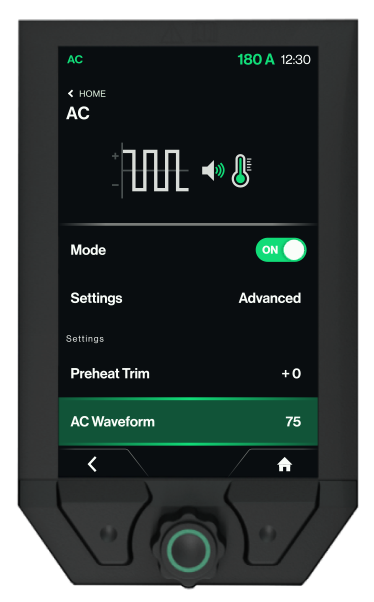
Selectable AC waveform characteristics affecting arc stability, cleaning action, and tungsten behavior. Square wave provides maximum cleaning efficiency with sharp current transitions and consistent oxide removal. Sine wave offers smoother arc characteristics with reduced tungsten heating but less aggressive cleaning. Advanced waveforms may include soft square, triangle, or custom shapes optimized for specific aluminum alloys and applications.
Micro-adjustment of tungsten heating and arc initiation characteristics to optimize starting performance for specific applications. Compensates for tungsten type, grinding angle, material cleanliness, and environmental conditions. Higher settings for difficult starting conditions or contaminated surfaces; lower settings for sensitive applications or to extend tungsten life. Provides fine-tuning beyond standard HF energy settings.
Tungsten electrode diameter setting that enables automatic optimization of current limits, gas flow rates, and arc characteristics. Machine databases contain current carrying capacity, optimal sharpening angles, and performance parameters for each diameter. Prevents tungsten overheating and ensures optimal arc performance. Common sizes: 1.0mm (5-75A), 1.6mm (10-150A), 2.4mm (40-250A), 3.2mm (80-400A), 4.0mm (150-500A).
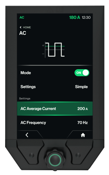
Frequency of alternating current cycles, affecting arc characteristics, cleaning action, and tungsten behavior. Higher frequencies (100-400 Hz) create more focused, stable arcs with reduced tungsten wandering, ideal for precision work and thin materials. Lower frequencies (50-120 Hz) provide broader cleaning action and better oxide removal for thick or heavily contaminated aluminum. Standard 60 Hz for general applications.
Independent amplitude control of positive and negative current phases in AC welding, allowing optimization of cleaning versus penetration characteristics. Increased positive current for heavy oxide cleaning; decreased positive current to reduce tungsten heating and extend electrode life. Negative current controls penetration depth and bead profile. Advanced machines allow independent control of both phases for precise heat input and cleaning optimization.
Percentage of time spent in positive (cleaning) versus negative (penetrating) portions of AC cycle. Standard 50/50 balance for general aluminum welding. Increased positive time (60-70%) for heavily oxidized or thick oxide layers. Decreased positive time (30-40%) for thin materials or when minimizing tungsten heating. Affects heat input distribution, oxide cleaning effectiveness, and tungsten life. Range typically 30-70% positive.
Maximum current level during positive half-cycle of AC welding, primarily used for aluminum and magnesium alloys. Positive current provides oxide cleaning action through cathode bombardment while negative current provides penetration. Balance between cleaning and penetration determined by current balance and time balance settings. Critical for achieving proper oxide removal without excessive tungsten heating or workpiece melting.
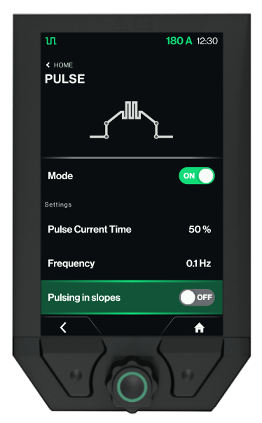
Allows pulse operation during slope-up and slope-down phases rather than only during main welding current phase. Provides enhanced heat input control during transition periods, particularly beneficial for thick sections requiring gradual heating and cooling. Helps prevent thermal shock, reduces residual stresses, and improves overall weld quality. Can be independently controlled for slope-up, main welding, and slope-down phases.
Number of complete pulse cycles per second, determining bead appearance and heat input characteristics. Higher frequencies (5-20 Hz) create smoother bead appearance with less distinct ripples, suitable for cosmetic applications. Lower frequencies (0.5-3 Hz) create pronounced ripple patterns with better heat input control for thick sections. Optimal frequency depends on travel speed, material thickness, and desired bead characteristics.
Time duration of high current phase in each pulse cycle, controlling the ratio of penetration time to cooling time. Longer pulse times increase average heat input and create wider, flatter bead profiles. Shorter pulse times provide more controlled heat input with distinct ripple patterns. Typical range 10-90% of total cycle time, optimized based on material thickness, desired bead appearance, and penetration requirements.
Lower current level maintained between pulses to keep arc stable without excessive heat input. Provides arc maintenance, prevents tungsten oxidation, and maintains weld pool fluidity during cooling phases. Typically 20-60% of pulse current. Higher base currents maintain larger weld pools and improve bead appearance; lower settings reduce overall heat input for thin materials and minimize distortion.
Higher current level during pulse phase of pulsed TIG welding, providing controlled penetration and bead profile formation. Creates the characteristic ripple pattern and controls fusion characteristics. Typically 150-400% of base current depending on application requirements. Higher pulse currents increase penetration and bead width; lower settings provide more controlled heat input for thin materials or precise applications.
Interval between consecutive tacks in repetitive tack welding mode, determining tack spacing along the joint. Pause time must account for travel speed, desired tack spacing, and cooling time between tacks. Longer pauses allow greater travel distance and prevent overlap heating; shorter pauses provide closer tack spacing for better joint control. Coordinated with welding sequence requirements and joint accessibility.
Individual tack duration in repetitive tack welding cycles, controlling the size and strength of each automated tack. Coordinated with travel speed and spacing requirements to ensure adequate joint preparation. Shorter times for thin materials or close spacing; longer times for thick sections requiring stronger temporary joints. Automatic timing ensures uniform tack quality throughout the joint length.
Current setting for repetitive automated tack welding sequences, allowing consistent tack quality during production fit-up operations. Can differ from manual tack current to optimize for automated timing and spacing requirements. Integrated with rep-tack timing controls to provide hands-free tack welding along joint length with predetermined spacing and consistency. Ideal for long seam preparation and production welding sequences.
Fixed time duration for tack current application, controlling tack weld size and penetration independently of welder technique. Longer times create larger, stronger tacks but increase heat input and potential distortion. Range typically 0.1-5.0 seconds with 0.3-1.0 seconds common for most applications. Automatic timing ensures consistent tack quality and eliminates operator variation in tack welding procedures.
Lower current setting specifically for tack welding operations, providing sufficient fusion to hold joint alignment without full penetration or excessive heat input. Typically 30-60% of full welding current depending on material thickness. Prevents distortion during fit-up while ensuring adequate strength for subsequent welding operations. Can be activated via special tack trigger sequence or dedicated tack button.
Dynamic arc control that adjusts current response to maintain consistent arc length and prevent electrode sticking during stick welding. Higher settings provide more aggressive arc dig for thick materials and out-of-position welding. Lower settings give smoother operation for thin materials and wash passes. Works with arc voltage feedback to automatically compensate for welder technique variations and maintain optimal arc characteristics.
Temporary current increase above set welding current during initial 0.5-2.0 seconds of stick electrode arc starting to overcome electrode coating resistance and prevent electrode sticking to workpiece. Boost typically 10-40% above welding current. Particularly important for basic (low-hydrogen) electrodes, large diameter electrodes, and when starting on cold or contaminated surfaces. Auto-adjusts based on electrode type and diameter settings.
Inert gas coverage duration after arc termination, protecting the hot weld metal and heat-affected zone from atmospheric contamination during cooling. Essential for reactive metals and high-temperature applications. Duration depends on material type, thickness, and cooling rate: aluminum 5-15 seconds, stainless steel 3-10 seconds, titanium 15-30 seconds. Insufficient post-gas causes discoloration, porosity, and reduced corrosion resistance.
Reduced current level maintained during final crater filling phase before complete arc extinguishing. Provides sufficient heat to keep weld pool molten for proper crater geometry while preventing excessive heat input. Should be 10-50% of welding current depending on material thickness and crater sensitivity. Critical for preventing crater cracks in aluminum and stress-corrosion cracking in stainless steels.
Controlled current reduction from welding current to end current, allowing gradual cooling and proper crater filling to prevent crater cracks and hot cracking. Longer slope-down times for thick sections prevent rapid thermal shock and reduce residual stresses. Critical for crack-sensitive materials like carbon steel, stainless steel, and aluminum alloys. Range 0.1-10.0 seconds.
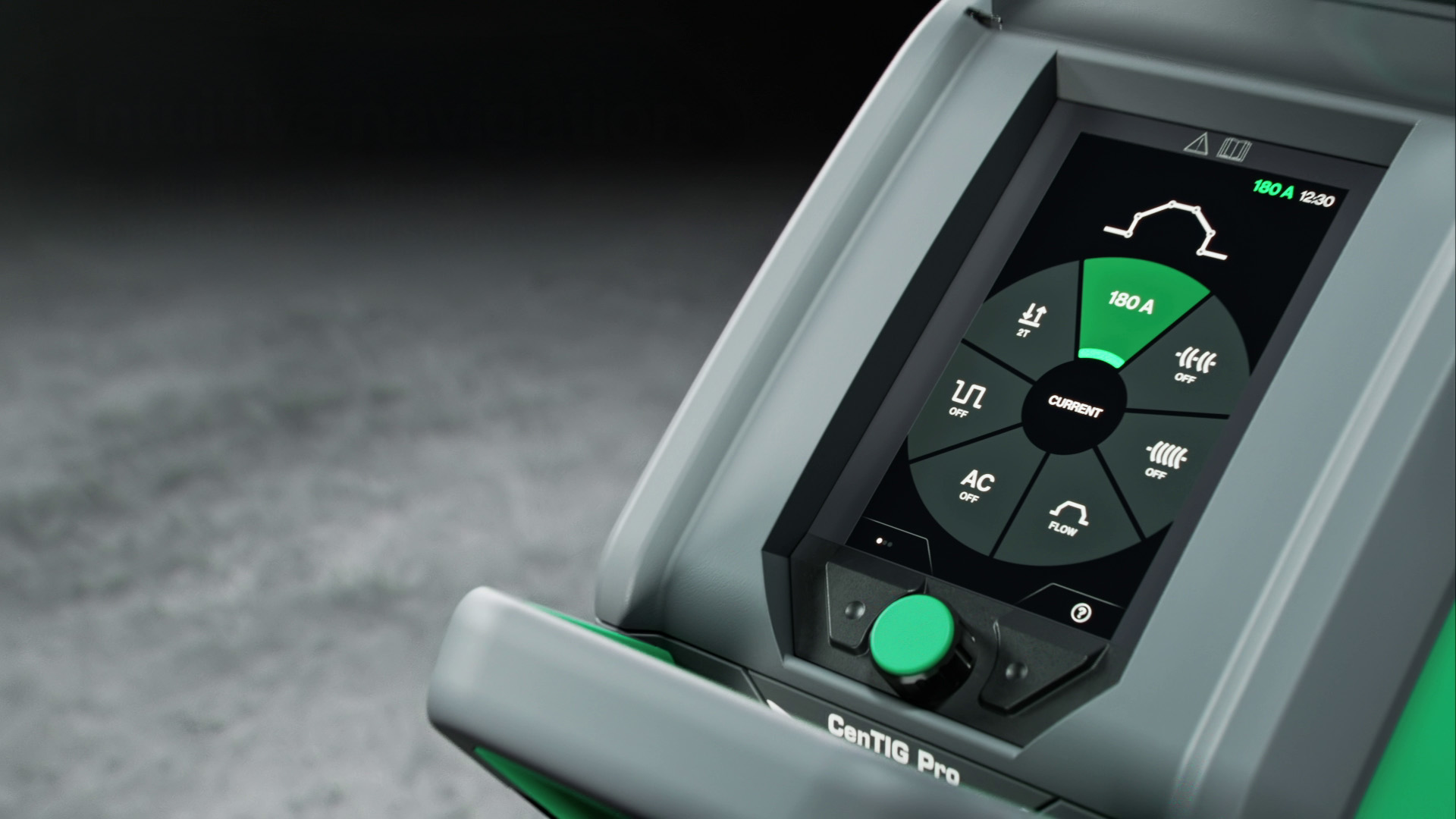
Primary welding current that determines penetration depth, bead width, and deposition rate. Must be matched to material thickness, joint design, tungsten diameter, and desired travel speed. Too low results in lack of fusion and cold lap; too high causes excessive penetration, undercutting, and heat distortion. Relationship with tungsten diameter: 1.6mm = 10-150A, 2.4mm = 40-250A, 3.2mm = 80-400A.
Optional intermediate current level during slope-up phase, creating a two-stage heating process particularly beneficial for thick sections or dissimilar metals. Allows controlled heat input progression: start current for arc establishment, secondary current for initial penetration, then max current for full joint penetration. Useful in root pass welding and when transitioning between different material thicknesses.
Controlled current increase from start current to welding current, allowing gradual heat buildup in the base material. Prevents thermal shock, blow-through on thin sections, and tungsten damage from sudden high current. Longer slopes for thick materials allow deeper preheat penetration. Range typically 0.1-10.0 seconds, with 1-3 seconds common for most applications.
Lower current level that establishes arc stability before ramping to welding current, preventing blow-through on thin materials and tungsten overheating on thick sections. Should be 10-30% of welding current depending on material thickness and tungsten size. Essential for precise heat input control and preventing initial weld defects like undercutting or lack of fusion.
Establishes inert atmosphere before arc ignition by displacing atmospheric oxygen and moisture from the weld zone. Critical for reactive metals like titanium, aluminum, and stainless steel. Longer pre-gas times needed for larger tungsten diameters, higher flow rates, or when welding in drafty conditions. Typical range 0.1-5.0 seconds, with 0.5-1.0 seconds standard for most applications.
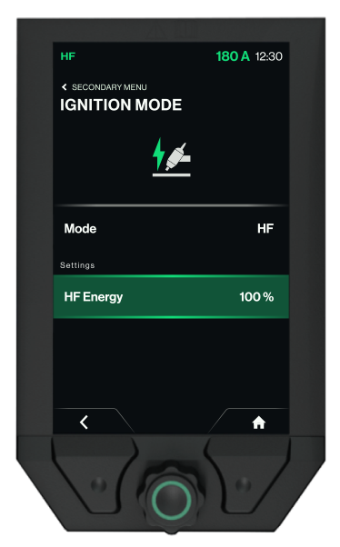
Adjusts the amplitude and duration of high-frequency energy output to match starting conditions and minimize electromagnetic interference. Higher settings overcome oxide layers, contamination, or larger tungsten-to-work distances. Lower settings reduce EMI for sensitive environments and extend HF transformer life. Range typically 1-10 with automatic shutoff after arc establishment.
High-frequency arc initiation creates an ionized path between tungsten and workpiece without physical contact, preventing tungsten contamination and maintaining point geometry. Essential for AC welding of aluminum where tungsten contact would cause immediate contamination. Frequency typically 2-4 MHz with spark gap bridging capability up to 6mm depending on conditions.
Lift arc ignition eliminates high-frequency interference by establishing the arc through brief tungsten-to-workpiece contact followed by lifting. Tungsten is quickly raised 2-3mm to maintain arc gap. Preferred in sensitive electronic environments, when HF causes interference with nearby equipment, or when welding in confined spaces where HF reflection could be problematic.
Advanced trigger sequence providing four distinct phases: 1) Press/release to start pre-gas and current ramp-up to welding current, 2) Weld at set current level hands-free, 3) Press to initiate slope-down sequence, 4) Release to complete end current and post-gas. Ideal for long welds, consistent production work, and when welders need free hand movement during welding.
Simple trigger operation where pressing the torch button initiates the arc with pre-gas flow, start current, and slope-up sequence. Releasing the button immediately begins slope-down, end current, and post-gas sequence. Best for short welds, repairs, and when maximum control over arc timing is needed. No intermediate steps or current holds.